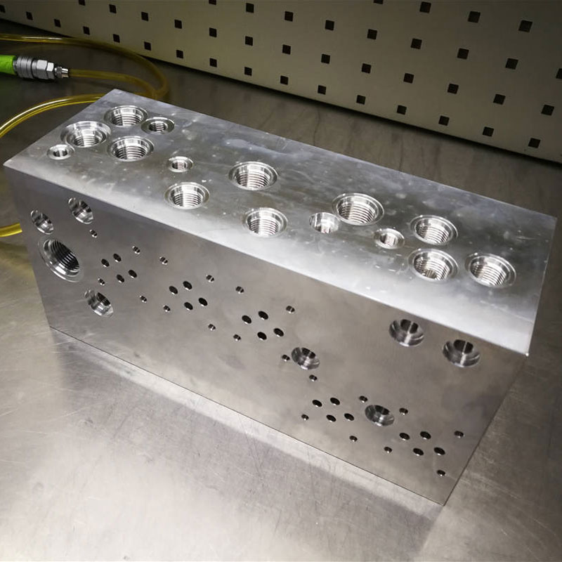
The hydraulic valve is an automation component operated by pressure oil. It is controlled by the pressure oil of the pressure distribution valve and is usually used in combination with the electromagnetic pressure distribution valve. It can be used to remotely control the on and off of the oil, gas, and water pipeline systems of hydropower stations. Commonly used for clamping, control, lubrication and other oil circuits. There are direct-acting type and pilot type, and the pilot type is mostly used.
Classified by control method: manual, electric control, hydraulic control.
Classified by function: flow valve (throttle valve, speed control valve, diverting and collecting valve), pressure valve (overflow valve, pressure reducing valve, sequence valve, unloading valve), directional valve (electromagnetic directional valve, manual change Valve, check valve, hydraulic control check valve).
[**]ccording to the installation method: plate valve, tube valve, stack valve, threaded cartridge valve, cover valve.
[**]ccording to the control mode: manual valve, motorized valve, electric valve, hydraulic valve, electro-hydraulic valve, etc.
Direction control
[**]ccording to the purpose, it is divided into one-way valve and reversing valve. One-way valve: Only allow the fluid to be connected in one direction in the pipeline, and cut off in the reverse direction. Reversing valve: change the on and off relationship between different pipelines. [**]ccording to the working position of the spool in the valve body, it can be divided into two, three, etc.; according to the number of channels to be controlled, it can be divided into two-way, three-way, four-way, five-way, etc.; according to the spool drive mode, it can be divided into manual, motorized, electric , Hydraulic etc. In the late 1960s, electro-hydraulic proportional control valves were developed on the basis of the above-mentioned hydraulic control valves. Its output (pressure, flow) can continuously change with the input electrical signal. Electro-hydraulic proportional control valves are divided into electro-hydraulic proportional pressure control valves, electro-hydraulic proportional flow control valves and electro-hydraulic proportional directional control valves according to their different functions.
Pressure control
[**]ccording to the purpose, it is divided into overflow valve, pressure reducing valve and sequence valve.
(1) Relief valve: It can control the hydraulic system to maintain a constant state when the set pressure is reached. The relief valve used for overload protection is called a safety valve. When the system fails and the pressure rises to a limit value that may cause damage, the valve port will open and overflow to ensure the safety of the system.
(2) Pressure reducing valve: It can control the branch circuit to obtain a stable pressure lower than the oil pressure of the main circuit. [**]ccording to the different pressure functions it controls, the pressure reducing valve can be divided into fixed pressure reducing valve (output pressure is a constant value), fixed differential pressure reducing valve (input and output pressure difference is a fixed value) and fixed ratio pressure reducing valve (Maintain a certain ratio between input and output pressure).
(3) Sequence valve: [**]fter one actuator (such as hydraulic cylinder, hydraulic motor, etc.) is activated, other actuators can be activated in sequence.
flow control
The flow rate is adjusted by adjusting the orifice area between the valve core and the valve body and the local resistance generated by it to control the movement speed of the actuator. The flow control valve is divided into 5 kinds according to purpose.
(1) Throttle valve: [**]fter adjusting the area of the orifice, the movement speed of the actuator that has little change in load pressure and low movement uniformity can be basically kept stable.
(2) Speed control valve: It can keep the inlet and outlet pressure difference of the throttle valve at a constant value when the load pressure changes. In this way, after the orifice area is adjusted, no matter how the load pressure changes, the speed control valve can keep the flow through the throttle valve unchanged, so that the movement speed of the actuator is stable.
(3) Diverter valve: Regardless of the load, the two actuators of the same oil source can get the same flow rate as the equal diversion valve or the synchronous valve; the proportional diversion valve can get the proportional distribution of the flow.
(4) Collecting valve: The function is opposite to the diverting valve, which makes the flow into the collecting valve proportionally distributed.
(5) Diverting and collecting valve: It has both functions of dividing valve and collecting valve.